Retaining wall design · Bedfordale WA
In short: The client needed structural drawings for two connected retaining walls in Bedfordale WA, up to 1.7 m high, with limestone blocks in front of interlocking concrete blocks. We designed the reinforced concrete base, the drainage and the design limits in a six-sheet drawing set, giving the builder the sections and site checks needed to build the walls.
- Service
- Retaining wall design
- Location
- Bedfordale WA
- Completed
- October 2026
- Walls
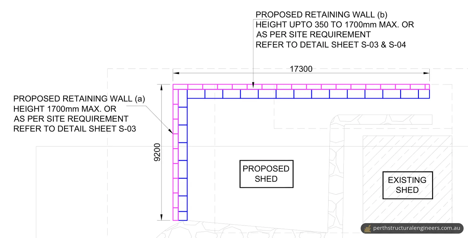
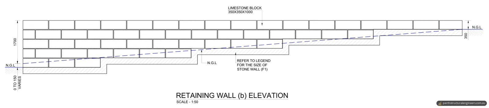
- Two connected walls: (a) 9.2 m long and up to 1700 mm high; (b) 17.3 m long and 350 to 1700 mm high
- Wall construction
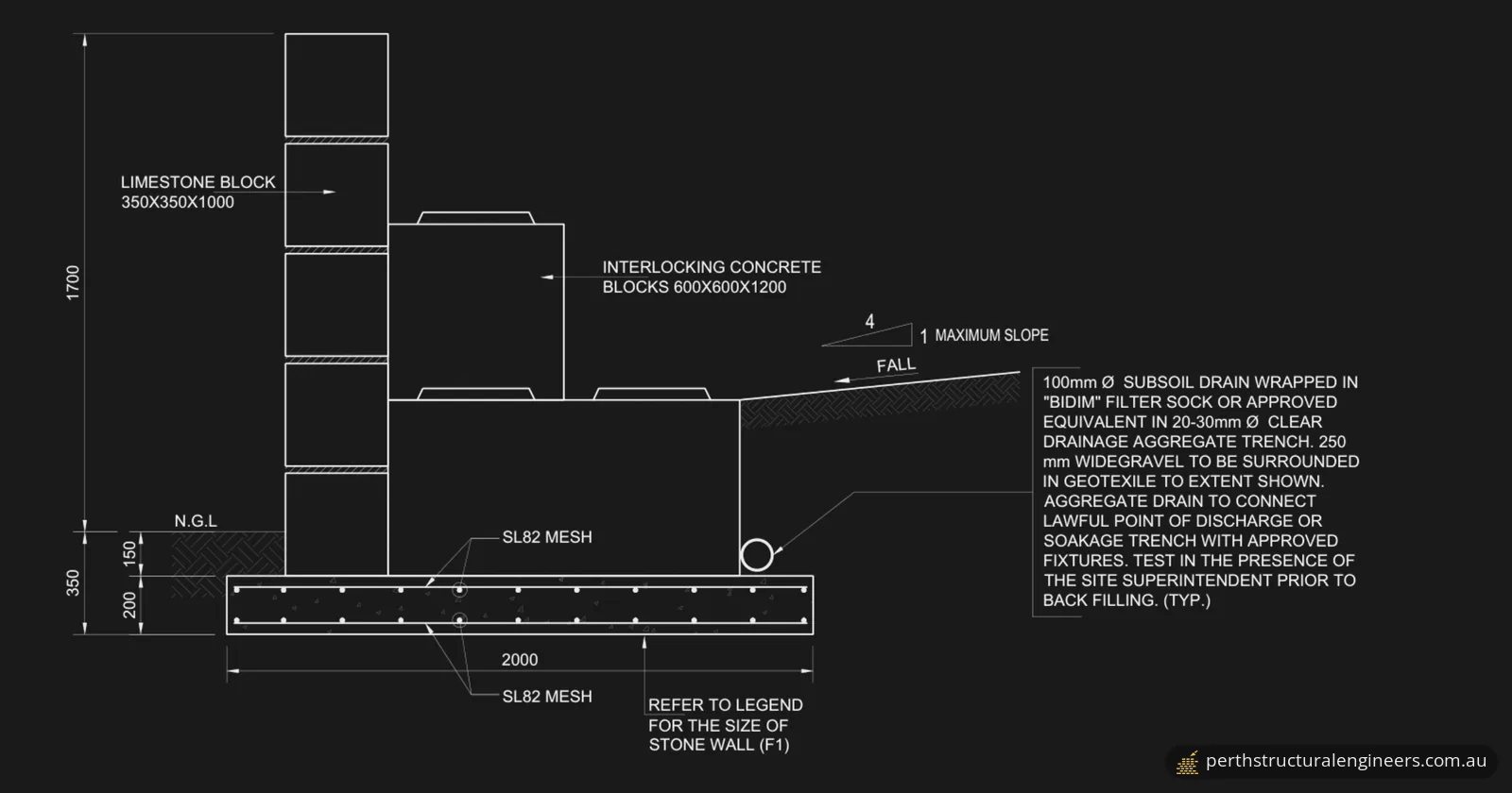
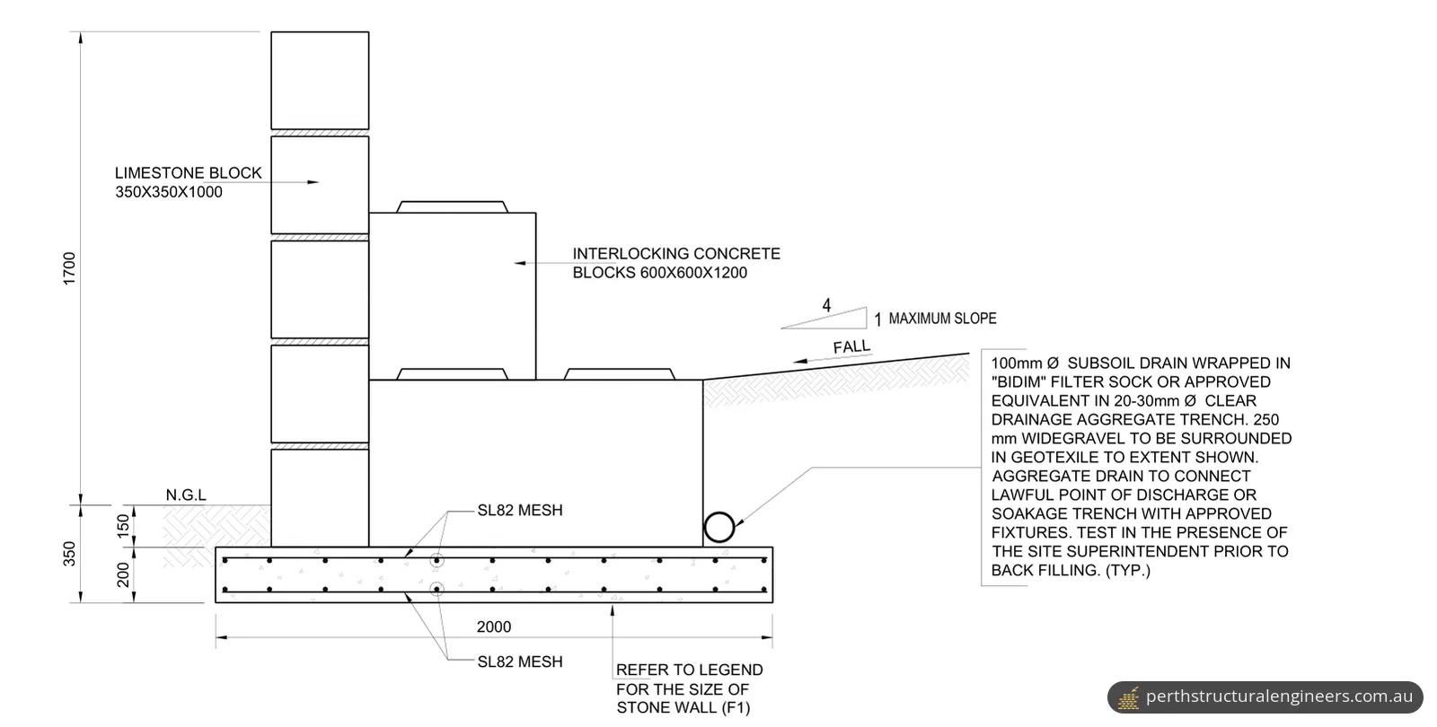
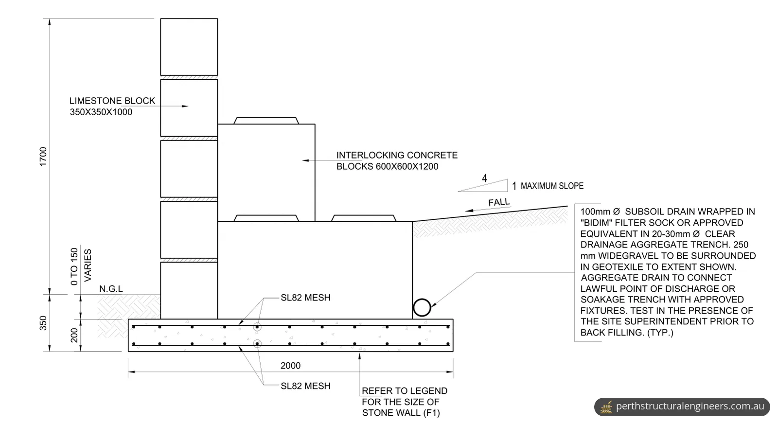
- 350 x 350 x 1000 mm limestone blocks in front of 600 x 600 x 1200 mm interlocking concrete blocks
- Base
- F1 concrete base, 2000 mm wide and 200 mm thick, with SL82 mesh top and bottom
- Drainage
- 100 mm subsoil drain in a filter sock and 20 to 30 mm clear drainage aggregate, to a lawful point of discharge or a soakage trench
- Soil class designed for
- Class M (presumed, to be confirmed by the contractor before excavation)
- Bearing capacity
- At least 150 kPa allowable, in stiff natural soil or rock
- Design basis
- AS 4678:2002; 22 kN/m³ retained backfill, Ka = 0.29, 2 kPa live load surcharge
- Design assumptions
- Fully drained walls and no structures at the rear of the walls
- Drawing set
- Six sheets, including the wall layout plan, sections for both walls and an elevation of wall (b)
The brief
The client needed structural drawings for new retaining walls at a property in Bedfordale WA, in the City of Armadale. The walls are up to 1.7 m high and are built from limestone blocks in front of interlocking concrete blocks.
The drawings had to show the builder how each wall is founded, built and drained, and what the design assumes about the ground and the loads behind it.
Why it needed a structural engineer
The City of Armadale's What can I build? page says a building permit may be required for retaining walls, and links to the City's retaining wall information sheet. That sheet says a building permit is required for retaining walls over 0.5 m in height, and that it must be obtained before any retaining wall works start. Its application checklist asks for construction details with cross-sections and a structural engineer's certification.
The walls on this job are up to 1.7 m high, more than three times that 0.5 m figure. The structural drawings set out the wall sections, the base and its reinforcement, the drainage, and the limits the design depends on.
What we designed
The drawing set has six sheets: a cover sheet, general notes, a site layout plan, the retaining wall layout plan, section details for both walls, and an elevation of wall (b).
- Two connected walls. Wall (a) is 9.2 m long and up to 1700 mm high. It meets wall (b), which is 17.3 m long and ranges from 350 mm to 1700 mm high. The layout gives both heights as maximums, or as the site requires.
- Blocks. Both walls use 350 x 350 x 1000 mm limestone blocks along the front of the base, with 600 x 600 x 1200 mm interlocking concrete blocks behind them.
- Base. The blocks stand on a concrete base (F1), 2000 mm wide and 200 mm thick, with SL82 mesh near its top and bottom. For wall (a), the top of the base is 150 mm below natural ground level. For wall (b), that depth varies from 0 to 150 mm.
- Stepped base. The elevation of wall (b) shows the top of the wall staying level while the base steps up along the wall as the natural ground rises.
- Drainage. A 100 mm subsoil drain wrapped in a filter sock runs behind the blocks, in a trench of 20 to 30 mm clear drainage aggregate, with the 250 mm wide band of gravel wrapped in geotextile. The drain connects to a lawful point of discharge or a soakage trench, and is tested in the presence of the site superintendent before backfilling.
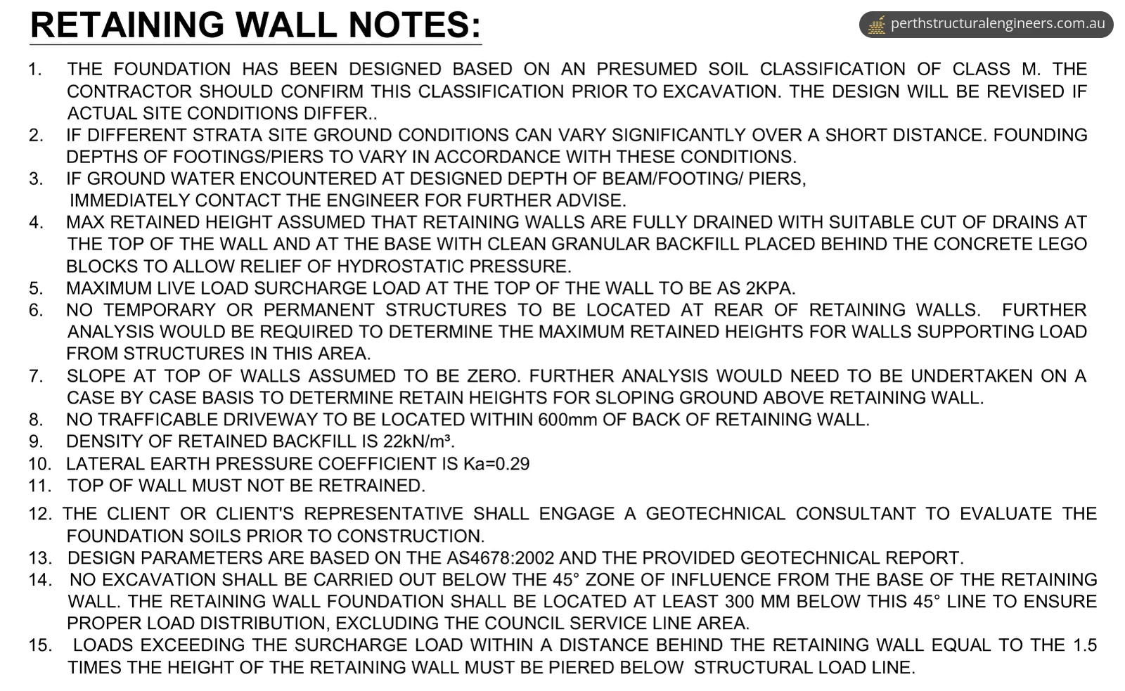
- Design basis. The design parameters are based on AS 4678:2002, Earth-retaining structures. The notes give a retained backfill density of 22 kN/m³, a lateral earth pressure coefficient (Ka) of 0.29 and a maximum live load surcharge of 2 kPa at the top of the wall.
- Fully drained walls. The maximum retained height assumes the walls are fully drained, with suitable drains at the top of the wall and at the base, and clean granular backfill behind the concrete blocks to relieve hydrostatic pressure.
- Ground above the walls. The sections show the ground behind each wall falling towards it at a maximum slope of 1 vertical to 4 horizontal. Note 7 assumes zero slope at the top of the walls and says sloping ground above a wall would need further analysis, case by case.
The notes also set what has to stay clear of the walls:
- No temporary or permanent structures are to sit at the rear of the walls. Walls supporting load from structures in that area would need further analysis.
- No trafficable driveway is to be within 600 mm of the back of a wall.
- Any load above the surcharge load within 1.5 times the wall height behind a wall must be piered below the structural load line.
- No excavation is to go below the 45° zone of influence from the base of a wall.
What has to be confirmed on site
The design depends on the ground, so the drawings list what the builder and the client must check:
- Soil class. The foundation is designed for a presumed Class M soil classification. The contractor should confirm it before excavation, and the design will be revised if actual site conditions differ.
- Founding depth. Ground conditions may vary significantly over short distances, so founding depths should be adjusted to suit them. Whatever depth is specified, all footings must extend into stiff natural soil or rock with a minimum allowable bearing capacity of 150 kPa.
- Geotechnical check. The client or their representative is to engage a geotechnical consultant to evaluate the foundation soils before construction.
- Groundwater. If groundwater is found at the design depth of the footings, the contractor must contact the engineer for advice.
- Dimensions. The builder confirms all dimensions, existing conditions, obstructions and limitations on site before ordering materials, and reports any discrepancies to the engineer.
The result
The client received the six-sheet drawing set. It gives the builder the block arrangement, base and drainage for both walls, the design values behind them, and the checks to make before and during construction. The general notes call for workmanship and materials to follow NCC 2022 Volume Two and local council requirements, and for construction to use plans stamped and approved by the building surveyor or relevant authority.
Planning a retaining wall in the Armadale area?
Our structural engineering services include retaining wall design, and we work across Armadale and its surrounding suburbs and the rest of our Perth service areas. Send us photos of the area, the heights you need to retain, any site plan or survey you have, and a soil or geotechnical report if there is one. You can request a quote online or call 1300 614 803.
Photos and drawings
From the report
Sample pages from what the client received (personal details removed).
Frequently asked questions
Do I need a building permit for a retaining wall in the City of Armadale?
Yes, for a retaining wall over 0.5 m in height. The City of Armadale's retaining wall information sheet says a wall built on a boundary between two or more properties may need a building permit regardless of height, and that the permit must be obtained from the City before any retaining wall works start. Planning approval may also be needed before a building permit can be issued.
What do I need to apply for a retaining wall building permit in Armadale?
The City of Armadale's checklist asks for a completed BA1 (certified) or BA2 (uncertified) application form, the fees, a site plan to scale (1:200) showing the wall, existing structures, boundary setbacks and any septic tanks or leach drains, construction details to scale (1:100) with cross-sections, a structural engineer's certification, and planning approval where it applies. A certified application must also come with a Certificate of Design Compliance issued by a registered independent building surveyor.
What does a Class M site classification mean?
In the NCC 2022 Housing Provisions, the Australian Building Codes Board's general definition of site classes describes Class M as moderately reactive clay or silt sites which can experience moderate ground movement from moisture changes. Its notes say Class M sites need further division based on the depth of expected movement, and that deep-seated movement, with a design depth of suction change of 3 m or more, is classified M-D.